
Publishing sonar readings with micro-ROS on the Raspberry Pi Pico

Jeremie Deray
on 10 June 2021
Tags: micro-ROS , Pico , Raspberry Pi , robotics , ROS2
Please note that this blog post has old information that may no longer be correct. We invite you to read the content as a starting point but please search for more updated information in the ROS documentation.
In this post, we will see how to wire up an HC-SR04 range sensor to the Raspberry Pi Pico and publish its readings to the ROS 2 graph using micro-ROS. This builds upon the previous post ‘Getting started with micro-ROS on the Raspberry Pi Pico’. As such, I’d encourage you to read it first if you are not already familiar with the topic.
A sensor you said?
In this tutorial, we will make use of one of the most common sensors in robotics, a sonar. These sensors are cheap, fairly simple to use and surprisingly precise under favorable circumstances. Sonars are used to measure distances. They can therefore be used to detect and locate obstacles, so that a robot can avoid nearby things. It is no mystery why they are so incredibly popular.
So, what’s a sonar, how does it work, which one should I pick?
“I’m Bat(sensor)”
A sonar is an echolocation sensor which allows for measuring distances. To keep things simple to digest, sonars work the same way as bats do. Nah they don’t fly, hunting bugs at dawn; nor do they fight crime. I obviously meant the same way as bats perceive the world. A sonar is composed of an emitter and a receiver. The former emits an ultrasound signal, which will bounce off of facing obstacles, back at the receiver. By measuring the time difference between the signal emission and reception, one can easily calculate the distance traveled by the sound wave, and thus, the distance to the obstacle that reverberated the sound.
This technology can suffer from all kinds of issues; if, for example, the sound wave is reverberated away from the sensor. Or if it is reverberated back to the sensor by two obstacles at different distances. Or if it is absorbed by some sound dampening material.
If this is still unclear or you want to know more about it, I’ll redirect you to your favorite web search engine as it is a little out of the scope of this post.
Which sonar model to pick?
There exist plenty of different models of sonars, fortunately most of them work the same way. Furthermore, they can be found for a few bucks per unit on the internet. Head on over to your favorite electronics supplier and you’re sure to find them for sale.
I’d recommend you use the ‘HC-SR04P’ model which is the 3.3V variant of the immensely popular ‘HC-SR04’ (5V). It is this model (the ‘HC-SR04P’) I will be using in this post. Given its very small power consumption, it can be powered up directly from the Pi Pico. The whole setup can thus simply be powered from the USB cable. In case you are using a 5V package, make sure to adapt the wiring described below or else you are risking damages to your Pi Pico! For reference, I ordered a lot of 5 units for less than $10 including shipping. Including the Pi Pico price, that’s a lot of sensing for the price!
Wiring up the sonar to the Pi Pico
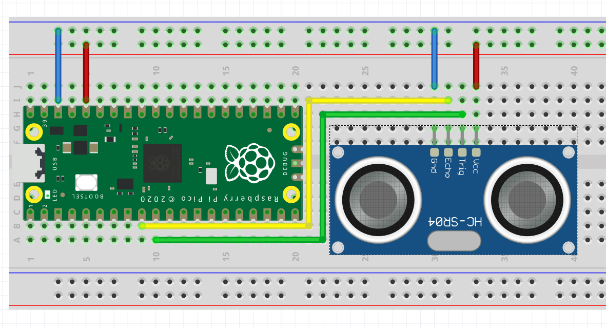
The ‘HC-SR04P’ board comes with four pins labelled ‘Vcc’, ‘Gnd’, ‘Trig’ and ‘Echo’. As you’ve already guessed, the Vcc and Gnd pins are for the 3.3V line and the ground respectively. ‘Trig’ is used to trigger the sensor and ‘Echo’ reports the reception of the echo (the reception of the wave that bounced off of an obstacle).
From there, and referring to the Pi Pico pinout, the wiring is straight forward:
- 3V3 OUT (pin 36) to the sonar’s ‘Vcc’
- GND (pin 38) to the sonar’s ‘Gnd’
- GPIO 6 (pin 9) to the sonar’s ‘Echo’
- GPIO 7 (pin 10) to the sonar’s ‘Trig’
This setup is depicted in the figure below.
As far as the hardware goes, we’re done. Let us move to software.
Micro code for micro-ROS on Pi Pico
We’ve seen in the previous post how to set up VSCode for programming micro-ros on the Raspberry Pi Pico, and how to compile and flash a program. We’ll thus jump directly for the main course, skipping all the boilerplate code and only show the bits specific to our application. However, know that this example (and more) is fully available on GitHub at artivis/mico_ros.
Alright, let’s dive in. Our application is essentially composed of two functions, one that triggers and reads the sensor, and a second, the timer callback, which calls the first, fill up a ROS message and publishes it:
// The GPIO pins to which the sonar is wired
#define GPIO_ECHO 6
#define GPIO_TRIGGER 7

/**
 * @brief Get the range value in meter.
 */
float read_range() {

  // Send an impulse trigger of 10us
  gpio_put(GPIO_TRIGGER, 1);
  sleep_us(10);
  gpio_put(GPIO_TRIGGER, 0);

  // Read how long is the echo
  uint32_t signaloff, signalon;
  do {
    signaloff = time_us_32();
  } while (gpio_get(GPIO_ECHO) == 0);

  do {
    signalon = time_us_32();
  } while (gpio_get(GPIO_ECHO) == 1);

  // Actual echo duration in us
  const float dt = signalon - signaloff;

  // distance in meter:
  // echo duration (us) x speed of sound (m/us) / 2 (round trip)
  return dt * 0.000343 / 2.0;
}

...

/**
 * @brief Read the range from the sensor,
 * fill up the ROS message and publish it.
 */
void timer_callback(rcl_timer_t *timer, int64_t /*last_call_time*/) {
  if (timer) {
    range_msg.range = read_range();
    fill_msg_stamp(range_msg.header.stamp);
    rcl_publish(&publisher, &range_msg, NULL);
  } else {
    printf("Failed to publish range. Continuing.\n");
  }
}
That’s pretty much it. The rest of the code is mostly boilerplate, initializing the GPIO, setting up the micro-ROS node, publisher, timer and executor, and having it all spin.
Note that we are using the standard ‘sensor_msgs/msgs/Range’ message. You can find its definition and a breakdown of its field online in the ROS 2 API documentation.
All there is to do now is to compile the code, flash the resulting ‘.uf2’ file and start the micro-ROS agent.
Bip bip bip
Assuming compiling and flashing went all fine, all we have to do is to plug the board to our computer and launch the micro-ROS agent. To do so, we use the following command:
docker run -it --rm -v /dev:/dev --privileged --net=host microros/micro-ros-agent:foxy serial --dev /dev/ttyACM0 -b 115200
Let’s see if we get anything,
$ ros2 topic list
/parameter_events
/pico/range
/rosout
The topic ‘/pico/range’ is advertised, that’s a good start. Let see what it contains,
$ ros2 topic echo /pico/range
header:
  stamp:
    sec: 145
    nanosec: 837599000
  frame_id: pico_sonar_0_link
radiation_type: 0
field_of_view: 30.0
min_range: 0.019999999552965164
max_range: 4.0
range: 12.138598442077637
---
header:
  stamp:
    sec: 145
    nanosec: 915356000
  frame_id: pico_sonar_0_link
radiation_type: 0
field_of_view: 30.0
min_range: 0.019999999552965164
max_range: 4.0
range: 12.138941764831543
---
That looks great!
You could now play with your new sensor, moving an obstacle back and forth in front of it. Take a measuring tape and compare the reported distance to the measured one. You may be surprised by its accuracy, I know I was.
What’s next?
This is a neat little project to approach micro-ROS on the Raspberry Pi Pico and the possibilities it opens. It is really rewarding to see the actual distance between the sensor and an obstacle being readily available on the ROS 2 graph. By taking a step back we can start seeing a slightly larger picture; a picture in which one will be able to easily, effortlessly, add plug and play ROS 2-ready hardware modules to existing robots. Plugging a camera and its feed magically appears on the graph. An IMU module could provide a reliable odometry source. A motor ready to spin in a snap (pun intended).
While we are not there yet, I’m definitely going to follow this line of thought for my own Turtlebot 3. Can you believe that it doesn’t have any sonar?!
Fortunately, now I can easily add a pair of them and have my robot stop bumping into my lazy cat lying down on the floor. Unwitting ninja, invisible to the laser scanner.
Before you go tinkering with micro-ROS on your Raspberry Pi Pico, make sure to subscribe to our newsletter so that you don’t miss any upcoming tutorial and more!
This post first appeared at artivis.github.io
Talk to us today
Interested in running Ubuntu in your organisation?
Newsletter signup
Are you building a robot on top of Ubuntu and looking for a partner? Talk to us!

Related posts
Discover your fully open source robotics observability at ROSCon 2025
Another year, another ROSCon! This year we’re heading to Singapore, and Canonical is once again thrilled to sponsor this important community event. Just like...
Canonical is now a platinum member in the Open Source Robotics Alliance
Ubuntu is the home of ROS. The very first ROS distribution, Box Turtle, launched on Ubuntu 8.04 LTS, Hardy Heron, and since then, Ubuntu and ROS have grown...
ROS Noetic is EOL – take action to maintain fleet security
As of May 2025, the Robot Operating System (ROS) Noetic Ninjemys officially reached its end of life (EOL). First released in 2020 as the final ROS (1)...